Contents |
Overview
WattNode® meters are available in seven voltage ranges up to 600 Vac line-to-neutral, as well as wide-range models that operate from 100 to 600 Vac. For service voltage above 600 Vac, potential or voltage transformers (PTs or VTs) are used to step down the voltage to a lower range that will work with a WattNode meter. PTs are used for medium-voltage services above 600 Vac, but also sometimes for 575-600 Vac three-phase three-wire delta circuits.
WattNode® for BACnet®, LonWorks, and Modbus meters support PT ratios and can scale measurements internally. Older models and pulse models will need to have the data scaled externally by the data collection system.
If you are using a WattNode® for LonWorks® meter, we offer Option PT, which adds a configuration property UCPTptRatio which configures the ratio of the external PT, allowing the meter to automatically scale the voltage, power, and energy readings.
Scaling
Adding potential transformers has the effect of reducing the measured line voltage by the PT ratio (let’s say 35:1 for this example). So a voltage of 4200 Vac becomes 120 Vac. Since the meter sees 120 Vac, many of the measurements it reports will be low by a factor of 35 unless they are scaled up by 35.
In particular, the following quantities are scaled by the meter or externally (if applicable for your meter):
- Voltage
- Power – since power is computed from the voltage and current. This includes all real, reactive, and apparent power values.
- Demand – this is the average power over an interval
- Energy – This includes all real, reactive, and apparent energy values. When using a pulse meter, multiply the kWh scale factor by the PT ratio.
The current, frequency, and power factor measurements are not affected by PTs.
Equipment
CCS supplies the WattNode meter rated up to 600 Vac and current transformers rated for use on circuits up to 600 Vac. CCS does not supply potential transformers, fuses, or CTs rated for use on medium-voltage circuits, so you will need to find other suppliers for these components.
Current Transformers
Continental Control Systems does not sell CTs rated for use over 600 Vac, so CTs rated for medium-voltage services must be used. Most medium-voltage CTs output 5 amps at their full scale rated current. For example, the secondary winding of a 500:5 ratio CT will output 5 amps when 500 amps flow through the CT’s window opening (primary). The 5 amp output of the ratio CT can be measured using one of our CTs to convert the 5 amp ratio CT’s output to a 0.333 Vac signal. Typical CTs for this application include:
- ACTL-0750-005 – Accu-CT® split-core CT
- CTT-0300-005 – solid-core (toroid) CT
We call this technique piggybacking. LonWorks meters (–FT10) are shown in the following drawings, but this piggybacking scheme works with any type of meter.
When piggybacking CTs, it is sometimes difficult to determine which direction the piggyback CTs should face. So just guess and install them all facing the same direction. If the power readings are minus or the status LEDs are flashing red, reverse the CTs, swap the black and white wires, or use the CtDirections register (Modbus models or the InvertCtA, InvertCtB, InvertCtC objects BACnet models) to effectively reverse the CT.
When you use two CTs together like this (a ratio CT combined with a voltage output CT), use the rated current of the ratio CT as the full-scale current rating value for the WattNode meter. For example, if the medium-voltage CT has a 500:5 ratio, use 500 as the full-scale current rating of the CTs.
Potential Transformer Circuits
This section describes the most common service types and PT circuits encountered. It provides recommended wiring diagrams and information on the measurements. In most cases, PTs are used with medium-voltage circuits ranging from 2400 Vac to 35,000 Vac, so this will show medium-voltage examples. The same circuits may also be used for lower or high voltage PTs.
Three-Wire Delta Service
Many medium-voltage services are three-wire delta services without a neutral conductor. These use one of the following grounding schemes:
- Floating: In many cases, delta wound transformers are left ungrounded. This has the advantage of allowing a ground fault on one of the phases from tripping the breaker and disrupting service.
-
-
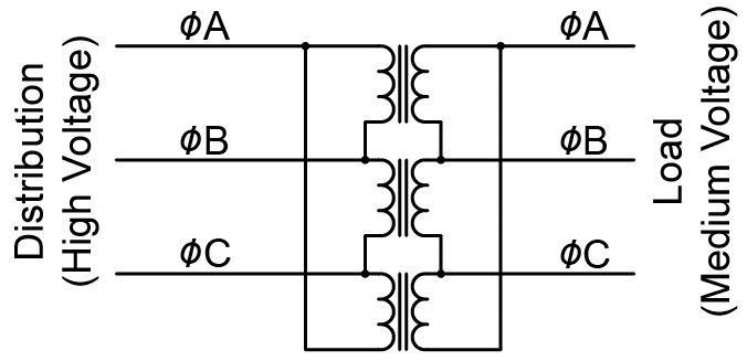

Figure 1: Utility Transformer: Delta-to-Delta Floating
-
- Corner Ground: One corner, typically phase B, is grounded.
-
-
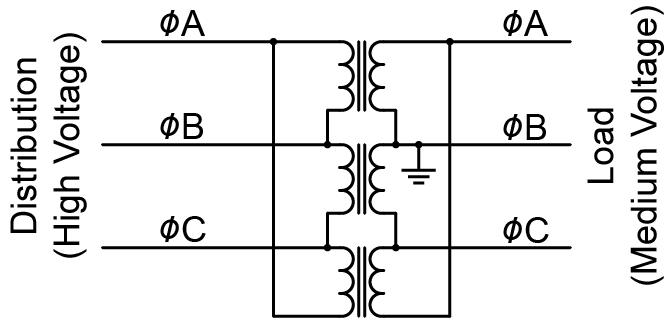
Figure 2: Utility Transformer: Delta-to-Delta With Corner Ground
-
- Center Ground: In this configuration, one winding is center-tapped and the center point tied to ground.
- Other: Other possibilities are possible (though uncommon) and include resistive grounding and inductive grounding.
All of the above grounding configurations (including floating) can be monitored as shown in Figure 3 below. This can use two or three element PTs. The third PT element is redundant (unnecessary) for this configuration and is shown in gray in the figure. As a result of grounding the phase B output of the PT, the WattNode meter will only report voltage, current, power, and energy for two phases: phase A and phase C.
Blondel’s theorem explains that the sum results (PowerSum and EnergySum) are accurate with this configuration. However, the reported power, reactive power, and power factor for the two individual phases may appear imbalanced, even if the actual load is balanced, so in this configuration, only the power and energy sums are meaningful.
For WattNode models that do not support delta circuits with 120 Vac line-to-line, you must wire the meter line-to-neutral. Therefore, we recommend using phase B as the reference and tying it to ground and neutral. This will result in zero readings for phase B from the meter.
Note, the PT primaries are monitoring the medium-voltage line-to-line voltages, so select the PT ratio based on the line-to-line voltages.
-
-
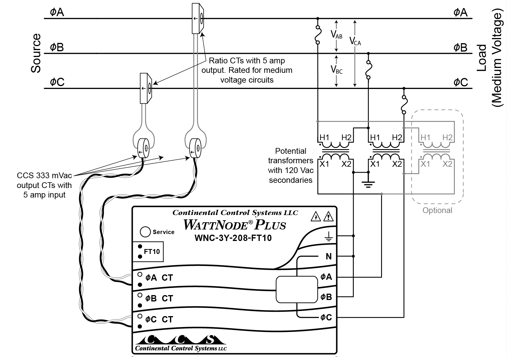
Figure 3: Monitoring a Delta Circuit
-
Four-Wire Wye Service
This is a medium-voltage wye service with a neutral conductor. The utility transformer may be a delta-wye (shown below) or a wye-wye transformer.
-
-
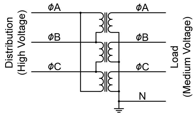
Figure 4: Utility Transformer: Delta-to-Wye
-
Four-wire wye service is monitored with the three-element PT configuration shown in Figure 5 below. The meter will provide per-phase voltage, current, power, and energy readings scaled to correspond to the medium-voltage measurements.
In this configuration, the PT primaries and secondaries are both wired in wye configurations. If either side of the PT were wired in a delta, it would cause a 30° voltage phase shift and incorrect readings.
Note, the PT primaries monitor the medium-voltage line-to-neutral voltages, not the line-to-line voltages. So be careful to select the correct PT ratio. For example, if the medium-voltage circuit is 4160/2400Y (2400 Vac line-to-neutral) you would need a 20:1 PT ratio to step the voltage down to 120 Vac.
-
-
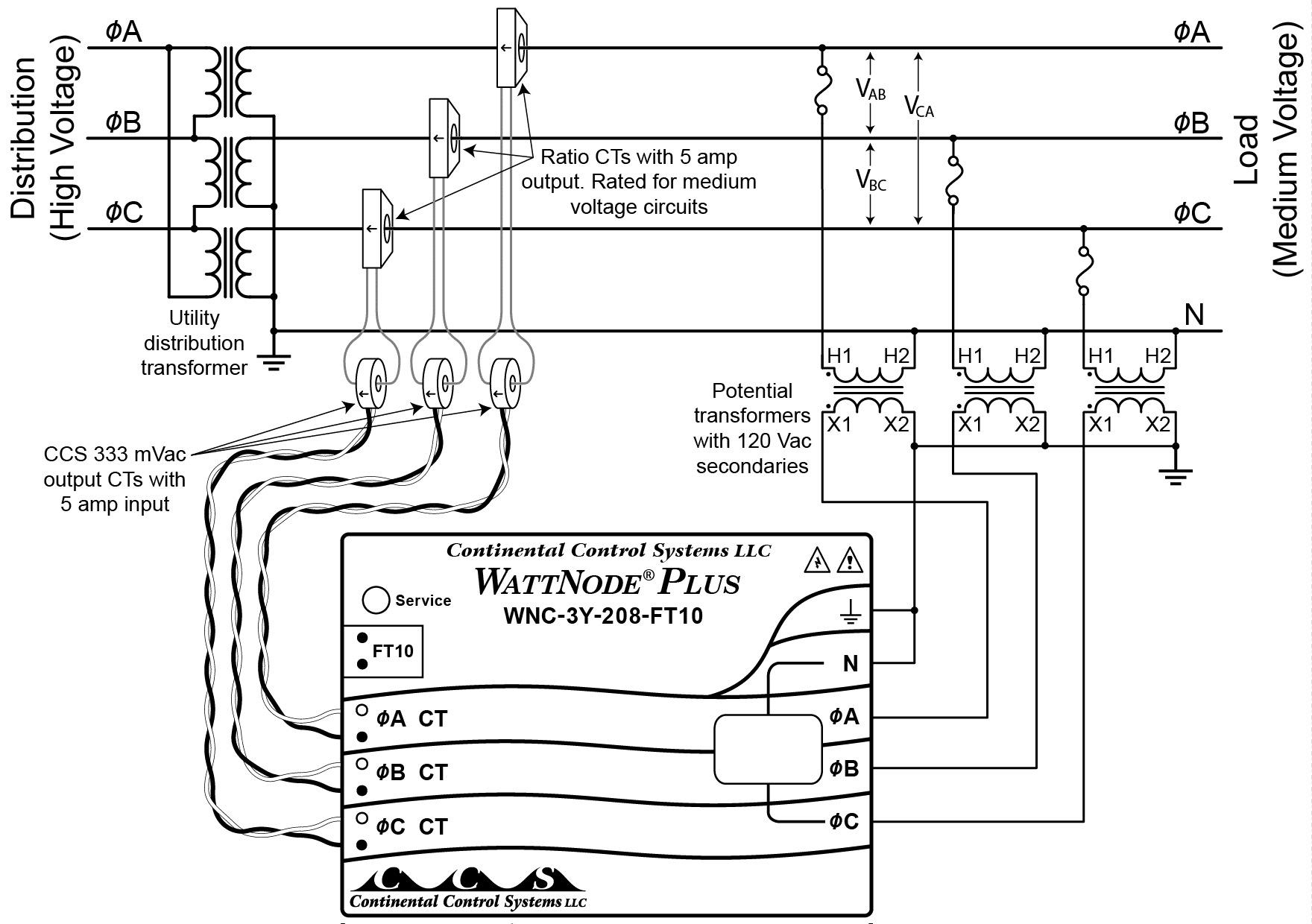
Figure 5: Monitoring a Four-Wire Wye Circuit With Neutral
-
Three-Wire Wye Service (No Neutral)
This is the same as the four-wire wye service except no neutral wire is brought out to the load. VA to ground, VB to ground, and VC to ground are all nearly equal. The ground potential is the same as neutral if neutral were used.
-
-
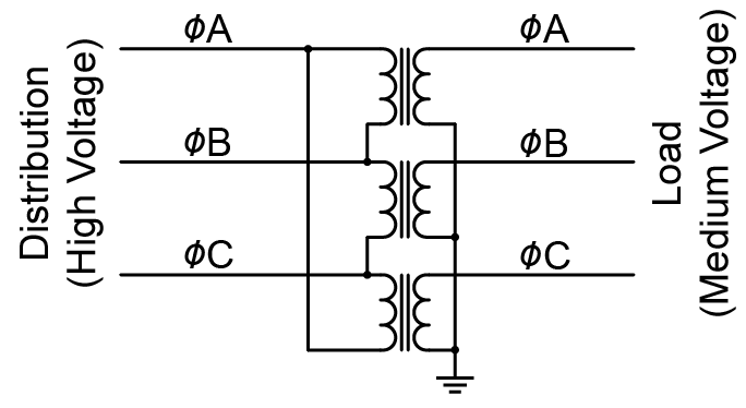
Figure 6: Utility Transformer: Delta-to-Wye Without Neutral
-
Three-wire wye service can be monitored with two different PT configurations.
- Two-Element PT: See Figure 3: Monitoring a Delta Circuit.
- Three-Element PT (Wye Output): This is the preferred PT configuration, because the meter will provide per-phase voltage, current, power, and energy readings for all three phases.
- In this configuration, the PT primaries and secondaries are both wired in wye configurations. If one side of the PT were wired in a delta, it would cause a 30° voltage phase shift and incorrect readings.
-
-
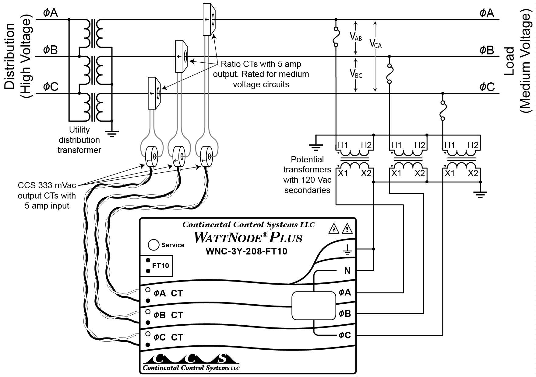
Figure 7: Monitoring a Three-Wire Wye Circuit without Neutral
-
Note, the PT primaries are monitoring the medium-voltage line-to-ground voltages, not the line-to-line voltages. So be sure to select the correct PT ratio. For example, if the medium-voltage circuit is a delta with 4160 Vac line-to-line, then the line-to-ground voltages will be 2400 Vac and you would need a 20:1 PT ratio to step down to 120 Vac.
Do not use the circuit in Figure 7 if the medium-voltage service does not come from a distribution transformer with a wye secondary, because the PT primary voltages may be indeterminate or mismatched.
Configuring the PT Ratio
Potential transformers convert medium (or high) utility voltages down to a lower voltage that is compatible with the WattNode meters. PTs are described by the step-down ratio as shown in the following table of common ratios.
| PT Primary Voltage |
PT Secondary Voltage (Line-to-Neutral) |
Pri:Sec = PT Ratio |
|---|---|---|
| 2400 | 120 | 2400:120 = 20 |
| 4200 | 120 | 4200:120 = 35 |
| 4800 | 120 | 4800:120 = 40 |
| 7200 | 120 | 7200:120 = 60 |
| 8400 | 120 | 8400:120 = 70 |
| 12000 | 120 | 12000:120 = 100 |
| 14400 | 120 | 14400:120 = 120 |
The PT Ratio values are just the primary voltage divided by the secondary voltage. For example, 4200 / 120 = 35. In rare cases, it is also possible to use a reverse PT to step up a lower voltage like 12 Vac to 120 Vac to enable a WattNode meter to monitor 12 or 24 Vac power consumption. This would result in PT ratios like 0.1 (12 Vac to 120 Vac) or 0.2 (24 Vac to 120 Vac). In the United States and Canada, most PTs have a secondary voltage of 120 Vac, so we have assumed that for this supplement. If your PT has a different secondary voltage, you will need to make sure the WattNode meter’s voltage rating matches the secondary voltage. The following table shows some possible PT secondary voltages and the associated WattNode models you would use.
| PT Secondary Voltage (Line-to-Line) |
PT Secondary Voltage (Line-to-Neutral) |
WattNode Model |
|---|---|---|
| 120 | 69 | Not supported |
| 208 | 120 | WNC-3Y-208-FT10 |
| 230 | 132 | WNC-3Y-208-FT10 |
| 400 | 230 | WNC-3Y-400-FT10 |
Note: Because CCS does not offer a model with a power supply that can operate from 120 Vac line-to-line or 69 Vac line-to-neutral, it may be necessary to tie one PT output voltage to neutral and ground as shown in Figure 3.
WattNode for LonWorks – Option PT
- See MS-20-WNC-LonWorks-Option-PT.pdf for more details about using PTs with WattNode for LonWorks meters.
If you have or are ordering a WattNode for LonWorks with Option PT, you can specify the PT ratio so that the meter will automatically scale the voltage, power, and energy values.
Once you have determined the correct PT ratio, program this into UCPTptRatio using LonMaker®, the WattNode LNS® Plug-In, or another LonWorks tool. UCPTptRatio is limited to the range 0.05 to 300. If you try to configure a value less than 0.05 or greater than 300, the meter will revert to a PT ratio of 1.0 (effectively no PT).
If you know the PT ratio at the time you are ordering the meter, you may specify the ratio as part of the option to have the ratio pre-programmed by the factory. For example, for a 4200:120 ratio PT, you would order the following:
-
- WNC-3Y-208-FT10 Opt PT=35
The value following the ‘PT=’ must be the ratio as a single number. Do not specify the primary voltage or two numbers separated by a colon.
If you do not know the PT ratio when you are ordering the meter, then add “Opt PT” to the model. The meter will ship with the PT ratio set to 1.0 and will need to be field configured.
WattNode Modbus and BACnet
WattNode Modbus and BACnet meters also support potential transformer ratios to scale voltage, power, and energy readings. Current and power factor do not need to be scaled by the PT ratio.
- Modbus registers 1639, 1640 PtRatio
- BACnet object #24 PtRatio
| WattNode Reading | PT Ratio | Scaled Value |
|---|---|---|
| 121.3 Vac | 35 | 4245.5 Vac |
| 4500 W | 35 | 157,500 W (157.5 kW) |
| 100 kWh | 35 | 3500 kWh |
WattNode Pulse
There is not an Option PT available for the WattNode Pulse meter. However, you can still connect the meter with potential transformers. You will just need to adjust the scale factors by the PT ratio. For example:
| Pulses Per Kilowatt-Hour |
PT Ratio | Scaled Pulses Per Kilowatt-Hour |
|---|---|---|
| 400 | 35 | 400 / 35 = 11.429 |
| 100 | 35 | 100 / 35 = 2.857 |
| Watt-Hours per Pulse |
PT Ratio | Scaled Watt-Hours per Pulse |
|---|---|---|
| 2.5 | 35 | 2.5 * 35 = 87.5 |
| 10 | 35 | 10 * 35 = 350.0 |
Notes
Energy Rollover
The WattNode for LonWorks and WattNode Modbus models have an internal energy rollover point of 100 GWh (100,000,000 kWh). When the energy reaches the rollover point, it rolls over to zero (like an odometer rolling around to zero). Generally it requires years to reach this rollover point, but with Option PT, rollovers could occur much more often.
For example, in an extreme case, with the maximum PT ratio of 300, 5000 amp current transformers, and a very high continuous load of 75% of maximum, the energy could reach 100 GWh in as little as 30 days.
A more realistic example might be a PT ratio of 60 (7200 Vac) and 2000 amp CTs, resulting in a rollover roughly once per year.
PT Burden
The WattNode meter will be powered from the PT secondaries, so you will need to select a PT with a high enough burden rating. WattNode models draw between 2 and 4 VA at a power factor (PF) between 0.6 and 0.8, and so require a potential transformer that is rated for that burden.
There are standard IEEE/ANSI C57.13 letter codes for PTs rated to handle different burdens. For non-standard PTs, check with the manufacturer.
- W: 12.5 VA @ 0.10 PF. WattNode meters draw far less than 12.5 VA, but the meter power factor is much higher than 0.10, so the accuracy of the PT might be affected.
- X: 25 VA @ 0.70 PF. This can easily supply a WattNode meter.
- M: 35 VA @ 0.20 PF. WattNode meters draw far less than 35 VA, but the meter power factor is higher than 0.20, so the accuracy of the PT might be affected.
- Y: 75 VA @ 0.85 PF. This can easily supply a WattNode meter.
- Z: 200 VA @ 0.85 PF. This can easily supply a WattNode meter.
Keywords: PT, PTs, potential transformer, VT, VTs, voltage transformer, instrument transformer