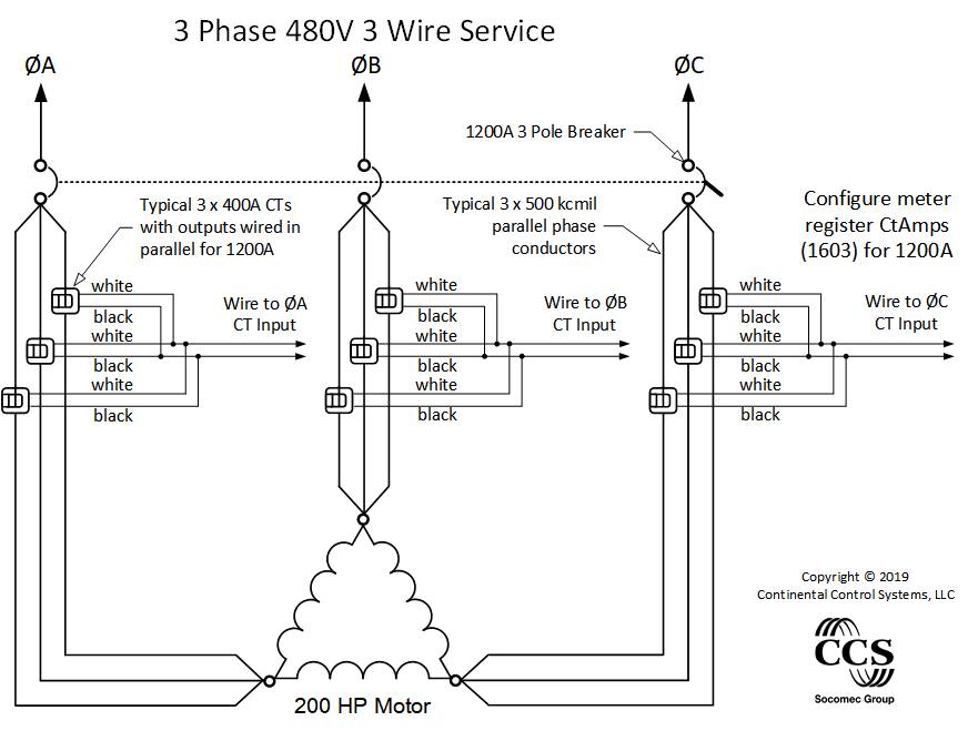
This page discusses the issues of using current transformers (CTs) in parallel. Below is a drawing that illustrates how CTs are wired in parallel. This is useful for the following:
- Circuits 400A and larger typically use sets of multiple parallel conductors for each phase. See Measuring Parallel Conductors.
- To measure multiple individual branch circuits or panels and add them together using one WattNode meter.
When paralleling CTs, the effective CT rated amps, CtAmps, is equivalent to the sum of the individual CT rated amps. So if you parallel two 100A CTs, the effective CtAmps is 200A. If you parallel three 50A CTs, the effective CtAmps is 150A. This works well for both balanced and imbalanced currents in the CTs wired in parallel. The accuracy will not be degraded if the rated amps of any individual CT is exceeded, so long as the total amps do not significantly exceed the combined rated amps.
The key to understanding how paralleling CTs works is to remember that the internal burden resistors of each CT are also in parallel (1/RBURDEN = 1/RCT1 + 1/RCT2) Each CT generates a secondary current proportional to its primary current. But when wired in parallel, the voltage drop across the smaller effective burden resistor is less.
Guidelines
- All parallel CTs must be exactly the same part number and rated current. Different CT models have different internal burden resistors, so combining them in parallel will not work correctly.
- Do not exceed the maximum amperage rating of any individual CT. See ACTL-0750 Maximum Amps and ACTL-1250 Maximum Amps.
- The CTRC Rogowski coil current sensors may be paralleled, but only before the conditioning circuit.
- Connecting CTs in parallel has a negligible effect on accuracy. In fact, parallel operation tends to average out the nominal errors of the individual CTs.
- Using CTs in parallel to to sum the currents in the individual phase conductors works well but there are some concerns:
- The more CTs connected in parallel the hard it gets detect and find wiring errors. Label each CT and its lead wires. Verify that each CT is facing in the right direction and on the correct phase conductor.
- The CT input terminal block fits a maximum of 3 #18 AWG wires. If connecting more than 3 CTs, use wire nuts or another type of approved splice and a short pigtail wire to connect to the CT input terminals.
- The combined wire length of many CTs can increases the risk of electromagnetic interference. CTs can be connected in parallel at the panel and a single twisted pair run to the meter.
- Add one set of CTs at a time, checking the WattNode output each time, to ensure none of the CTs are reversed or installed on the wrong phase.
- If possible, use a portable power analyzer to commission the installation.
See Also